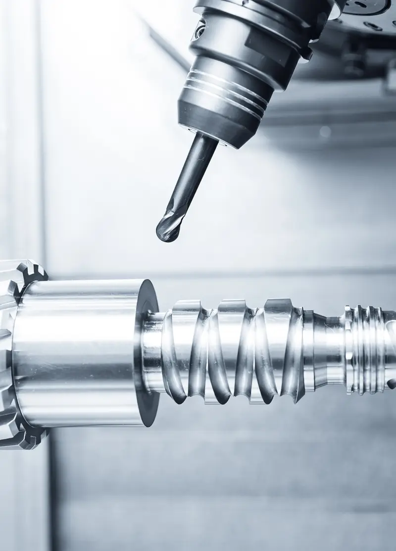
In deep slots and pockets, the hardest job you can give an end mill is full slotting: it cuts with its entire diameter at a 180° engagement angle, and heat and chips stay trapped in the slot. Trochoidal milling (called dynamic, adaptive or high-efficiency milling in most CAM systems) spreads that load by combining a small radial engagement with a large axial depth of cut. Set up correctly, it extends tool life and reduces the risk of breakage; set up badly, it only produces a long toolpath and wasted cycle time. This guide explains how the method works, how to choose a solid carbide end mill for it and which mistakes to avoid.
What is trochoidal milling?
Instead of driving straight through the slot, the tool follows a circular or looping path that advances along the feed direction. Each loop removes only a thin slice of material (small ae), while the axial depth (ap) can use a large part of the flute length, as far as the tool and machine allow. Classic trochoids repeat fixed circles; modern CAM strategies recalculate the path continuously so the engagement angle stays constant in corners and changing geometry. Both aim for the same thing: a similar, controlled load on the tool at every moment.
Why the engagement angle matters
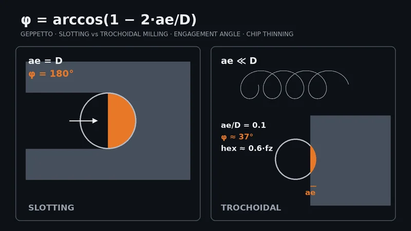
The engagement angle φ is the arc each cutting edge spends inside the material per revolution: φ = arccos(1 − 2·ae/D). In a full slot (ae = D), φ = 180°, so each edge cuts for half a revolution and has no chance to cool. At ae/D = 0.1, φ drops to about 37°: the edge cuts briefly, cools for the rest of the revolution and throws the chip into open space. Cutting forces are also lower and more uniform, which reduces deflection and chatter, especially with long tools.
Chip thinning: why you must raise the feed
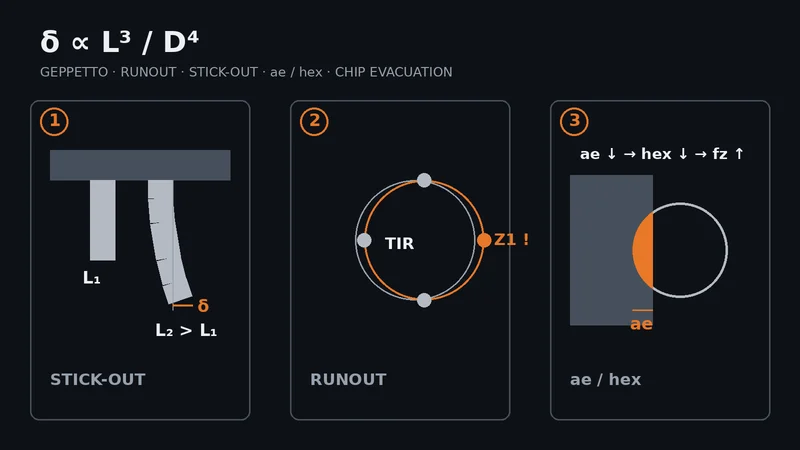
When the radial engagement is less than half the diameter, the real chip is thinner than the programmed feed per tooth (fz). The maximum chip thickness is approximately hex = fz · 2·√((ae/D)·(1 − ae/D)). At ae/D = 0.1, hex ≈ 0.6·fz, so fz must be raised by roughly 1.67× to keep the target chip thickness. If it is not, the edge rubs instead of cutting: heat rises, materials such as stainless steel and titanium work-harden, and the tool wears out faster than expected. You can run the numbers with our speed and feed calculator; start from the tool's catalogue data and confirm step by step on your machine.
Which carbide end mill to use
- Flute count: With small ae, each tooth removes less material, so 4–6 flute end mills are usually preferred; they allow a higher table feed at the same chip thickness. The flute space must still be sufficient.
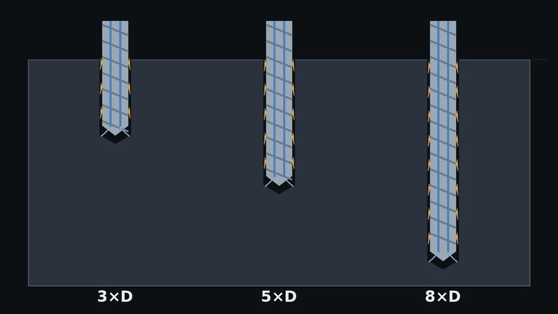
- Flute length and stick-out: Because ap is large, choose a flute length that matches the depth, but keep the stick-out from the holder no longer than necessary.
- Chipbreaker profile: Large ap produces long, thin chips; serrated (chipbreaker) roughing end mills split them and make evacuation easier.
- Corner radius: A sharp corner is the fastest-wearing point; if the part allows it, a small corner radius is safer.
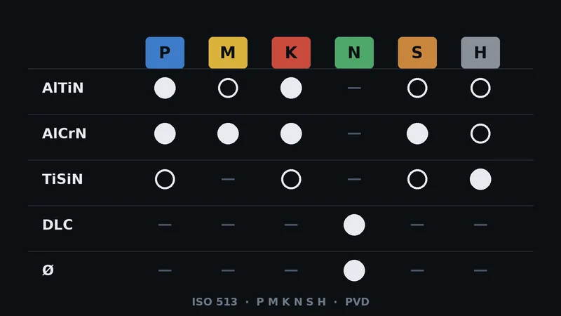
- Coating: AlTiN or AlCrN are common for steel and stainless, TiSiN for hardened steel; see our coating guide.
In the Geppetto catalogue, the series suited to this work are grouped on the carbide roughing end mills page: the MC series with an approx. 45° helix and the serrated MRS series, both in Z4 and Z6 versions. For all series, see our solid carbide end mills page.
Machine and CAM requirements
- Machine dynamics: The method needs high table feeds and frequent changes of direction. A machine with weak acceleration or look-ahead cannot reach the programmed feed; when the actual feed drops, the chip thins and rubbing starts.
- Slot width: The slot must be clearly wider than the tool diameter. In a slot barely wider than the tool, the loops shrink and the tool effectively works close to full slotting.
- Entry: Use a helical or ramp entry, or start from a pre-drilled hole, instead of plunging straight down.
- Chip evacuation: Re-cutting chips is one of the most common causes of breakage. Depending on the material, use air blast or generous coolant to clear chips from the cutting zone.
- Holding: Large ap puts a larger bending moment on the holder; a precision collet, hydraulic or shrink-fit holder and low runout matter.
When it makes sense, and when it doesn't
Trochoidal milling pays off in deep slots and pockets, in difficult materials such as stainless steel, titanium, heat-resistant alloys and hardened steel, on machines with limited rigidity and whenever you have to work with a long tool. In a short, shallow slot, the time spent cutting air can cancel the gain, and a conventional path may be faster. For tight-tolerance walls, plan a separate finishing pass after roughing, because small steps and deflection marks can remain. On thin-walled parts, remember that a large ap can also deflect the wall.
Tool life and regrinding
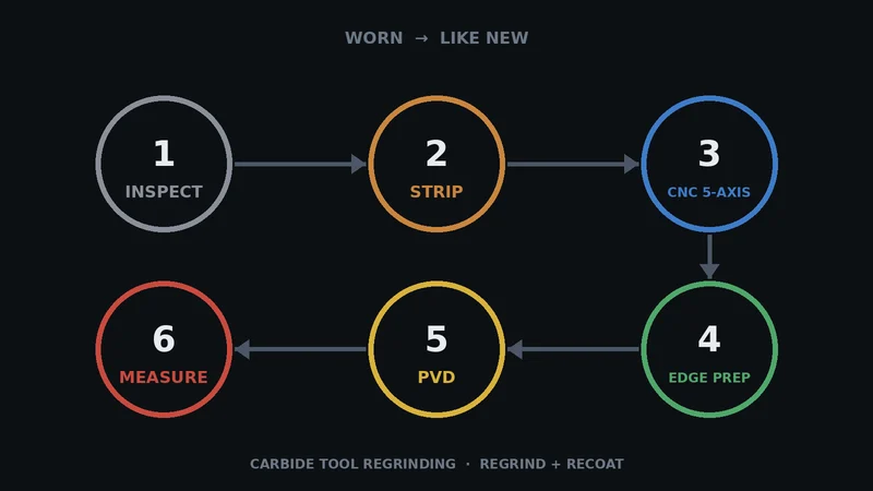
With large ap, wear is spread along the whole flute length instead of being concentrated in one zone. This makes it easier to remove the tool before it breaks, with an even wear land, and such a tool can often be reground and recoated. Regrinding has to account for wear along the full cutting length. See our regrinding guide and our regrinding service. If you are fighting chatter or breakage, our troubleshooting guide offers a step-by-step checklist.
Conclusion
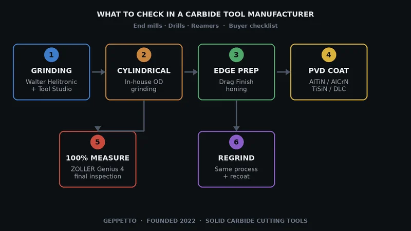
Success in trochoidal milling depends on getting several things right together: small ae, fz corrected for chip thinning, an ap the tool can carry, a suitable flute count and good chip evacuation. Geppetto is a solid carbide cutting tool manufacturer in Turkey: our end mills are ground on Walter Helitronic machines and measured on a ZOLLER Genius 4, and we supply both catalogue series and special tools with custom flute length and neck dimensions for international customers. Share your material, slot dimensions, machine and current tool and we will review the application with you: contact us, phone +90 216 394 41 10, WhatsApp +90 537 777 96 44, email info@geppetto-tr.com.
Frequently asked questions
What is trochoidal milling?
It is a milling method in which the tool follows a looping path that advances along the slot instead of driving straight through it. A small radial engagement (ae) and a large axial depth (ap) keep the load on the tool low and constant.
What radial engagement (ae) should I use for trochoidal milling?
There is no single value for every case; it depends on the material, tool geometry and machine. The general principle is to keep ae at a small fraction of the diameter and to raise fz for chip thinning as ae gets smaller. Start from the tool manufacturer’s catalogue data.
Why do I need to increase the feed?
When ae is less than half the diameter, the real chip is thinner than the programmed fz. At ae/D = 0.1, for example, the maximum chip thickness is about 0.6·fz. Without correction, the edge rubs, heats up and wears quickly.
Can every machine do trochoidal milling?
It can be applied on most CNC machines, but the machine must keep up with high feeds and frequent changes of direction. On a machine with low acceleration, the actual feed stays below the programmed value and the expected gain shrinks.
Which end mill is best for trochoidal milling?
Usually a 4–6 flute solid carbide end mill with a flute length matched to the depth, preferably with a corner radius and, at large ap, a chipbreaker (serrated) profile. The coating is chosen according to the workpiece material.
Does trochoidal milling increase tool life?
In most cases it does, because heat and load are spread out and wear is distributed along the flute length. Rubbing at too low a feed, poor chip evacuation or weak tool holding can cancel that advantage.